TLMBoy: Exploring the Game Boy's Boot
1. Introduction
This is another post of my TLMBoy series where I document the development of my equally named Game Boy Emulator. In contrast to my other posts, the following sections do not deal with any “How do I implement this and that?”. I rather dissect and explain the 256-byte hidden boot code that helps bringing up the Game Boy!
When turning on most compute systems, only a few things are guaranteed to have a certain value. The Game Boy is no exception and only guarantees the program counter register to be initialized with 0. All other things like other registers, the sound processor, and the pixel processing unit have to be initialized by the boot process.
In case of the Game Boy, the boot code resides within a special 256-byte ROM that is mapped from 0x00 to 0xff. Interestingly, the boot ROM unmaps itself from the memory map after finishing the boot. This demap feature made it quite hard to reverse engineer the boot code.
The first successful reverse engineering attempt was achieved by a dude(tte) called “neviksti” in 2003. This was 14 years after the initial release of the Game Boy in 1989! According to gbdev wiki [1] this person was actually mad enough decap the Game Boy’s SoC and read out every single bit using a microscope. Interestingly neviksti’s website [2] is still up today and features some cool die shots like this one:
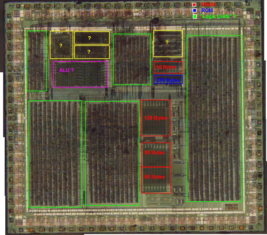
If you are interested in reading and interpreting bits of a ROM I can highly recommend this tutorial.
In the following sections, I’ll go through the boot code line by line and analyze it.
Furthermore, I’ll try to disassemble the assembly into some C-ish code.
Of course I’m a little bit late to the party and a lot of people wrote some nice wrapups before me. Take a look at the Literature to see what helped me writing this post.
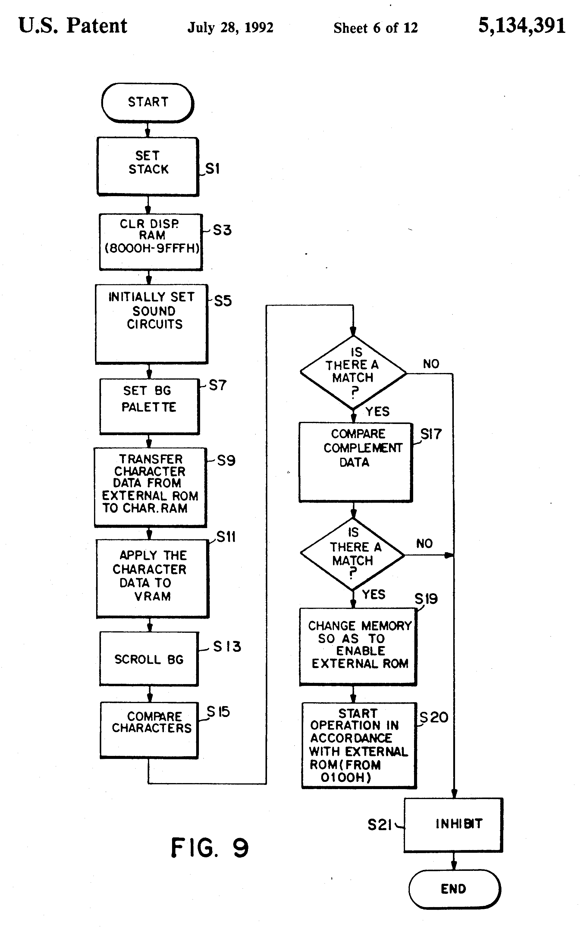
Also Nintendo themselves helped me
by putting their boot CFG (control flow graph) into a patent [3] called
“System for preventing the use of an unauthorized external memory”:
2. The Boot Code
Before analyzing the code, we do of course need some assembly code to work on! My personal favorite is this [4] commented, human-readable boot rom which I will refer to in the following.
2.1 BB0: Init Regfile
The first three instructions are some plain register initializations.
The stack pointer sp is set to 0xfffe; register a is set to 0; and hl now points to the VRAM (0x9fff).
BB0:
0x000  ld   sp, $fffe   // init stack
0x003  xor  a           // efficient way for: a = 0
0x004  ld   hl, $9fff   // set hl to VRAM
2.2 BB1: Init the VRAM
To avoid displaying random garbage, the Game Boy has to zero-initialize its VRAM. The following three-line loop takes care of it.
BB1:
0x007  ld   [hl-], a   // load a into [hl], then decrement hl
0x008  bit  7, h       // stop condition
0x00a  jr   nz, @BB1   // jump to BB1, if not zero
This quite dense code can be achieved by using a little bit-trick. The VRAM ranges from 0x8000 to 0x9FFF, whereby all these addresses in binary have a “1” bit at position 8 in the MSB. But the first number under 0x8000 doesn’t:
0b10000000 00000000 = 0x8000
0b01111111 11111111 = 0x7FFF
The same functionality can be achieved with the following C-Code:
for (int i = 0x9FFF; i >= 0x8000; --i) {
  mem[i] = 0;
}
2.3 BB2: Init the sound
The next lines setup the Game Boy’s sound processor:
0x00c  ld  hl, rNR52  // load 0xFF26 into hl: register no 52
0x00f  ld  c, $11
0x011  ld  a, $80
0x013  ld  [hl-], a   // rNR52 = $80, all sound on
0x014  ld  [c], a     // rNR11 = $80, wave duty 50%
0x015  inc c
0x016  ld  a, $f3
0x018  ld  [c], a     // rNR12 = $f3, envelope settings
0x019  ld  [hl-], a   // rNR51 = $f3, sound output terminals
0x01a  ld  a, $77
0x01c  ld  [hl], a    // rNR50 = $77, SO2 on, full volume, SO1 off, full volume
These lines setup the square wave channel for the iconic boot “bling bling” sound. I try not to get lost in details, as this setup is of minor relevance for the boot process. A corresponding C-Code could look like this:
mem[0xff26] = 0x80; // All sound on.
mem[0xff11] = 0x80; // Square wave: Wave duty 50%, don't use length register.
mem[0xff12] = 0xf3; // Square wave: Start at full volume (15), and then decrement every 3 envelope ticks until 0.
mem[0xff25] = 0xf3; // Sound output terminal.
mem[0xff24] = 0x77; // SO2 on, full volume, SO1 off, full volume
2.4 BB3: Init the color palette
As a next step, the background and window color palette register (BGP, at 0xff47) is set to 0b11111100, and the pointers for logo load are prepared.
0x01d  ld  a, $fc
0x01f  ldh [rBGP], a  // BGP = $fc, set up color palette
0x021  ld  de, $0104  // de = cartridge header logo
0x024  ld  hl, $8010  // hl = VRAM
The BGP setup can be translated as:
11 10 01 00 # value
|  |  |  |
11 11 11 00 # mapped to
|  |  |  |
b  b  b  w # b=black, w=white
It’s simply a remapping of color values for the background and window tiles. So, for a example, a pixel with the a value of 01 is displayed as 11, which is deep black (the reason for this mapping is explained in Subsection 2.7) The corresponding C-Code is just (ignoring the pointers):
mem[0xff47] = 0xfc; // set up BG and window color palette
2.5 BB4: Load the Logo
The job of the next basic block is to load the Nintendo logo from the cartridge into the VRAM:
BB4:
0x027  ld   a, [de]    // for loop over cartridge logo data, de = 0x104
0x028  call $0095      // copy cartridge logo data to VRAM at $8010
0x02b  call $0096
0x02e  inc  de
0x02f  ld   a, e
0x030  cp   $34        // a == 0x34?
0x032  jr   nz, @BB4
However, due to size constraints, the Nintendo logo is heavily compressed and needs to be decompressed by a relatively simple algorithm. That way the 48 Bytes of the compressed Nintendo logo can be inflated to 384 Bytes (=24 tiles) worth of pixel data. The corresponding C-Code looks like this:
u8 *vram = 0x8010;
for (u8 *logo = 0x0104; logo < 0x0134; ++logo) {
  u8 data = *logo;
  DecompressAndCopy(data, vram);
  vram += 4;
  DecompressAndCopy(data >> 4, vram);
  vram += 4;
}
// vram will be 80d0
In the following section, we will take a closer look at the decompression algorithm.
2.6 Decompress And Copy
The decompression algorithm of the Game Boy is not really complex, yet the assembly is quite:
// 'a' holds the next datum of the logo
DecompressAndCopy:
0x095   ld    c, a    // c = 76543210
0x096   ld    b, $04  // loop counter

decomp_loop:
0x098   push  bc
0x099   rl    c
0x09b   rla
0x09c   pop   bc
0x09d   rl    c
0x09f   rla
0x0a0   dec   b
0x0a1   jr    nz, @decomp_loop

0x0a3   ld    [hl+], a
0x0a4   inc   hl        // leave on byte blank
0x0a5   ld    [hl+], a
0x0a6   inc   hl        // leave on byte blank
0x0a7   ret
So, let’s start with an abstract description of what the algorithm actually does. As an input, the algorithm receives one byte of data (the numbers represent bit positions):
> in = 76543210
The output is then a scaled version (2x in x and y direction) distributed over 4 bytes:
> out0 = 77665544
> out1 = 77665544
> out2 = 33221100
> out3 = 33221100
I hope that this is as simple as I promised.
We now increase the difficulty and analyze the actual implementation.
The first call of the DecompressAndCopy calculates the first two bytes of the outputs (out0, out1),
while the second call calculates the last two bytes (out2, out3).
Note, that the second call uses 0x96 instead of 0x95 as an entry point due intermediate values still residing in register c.
To more make the code more accessible, I did a systematic analysis of the decomp_loop.
In the following table, each column represents an iteration of the decomp_loop, whereby the numbers uniquely identify
the bits (C stands for carry):
| instr | b = 4 | b = 3 | b = 2 | b = 1 |
|---|---|---|---|---|
| 0x99 | c=6543210x, C=7 | c=54321076, C=6 | c=43210754, C=5 | c=32107532, C=4 |
| 0x9b | a=65432107, C=7 | a=43210776, C=5 | a=21077665, C=3 | a=07766554, C=1 |
| 0x9c | c=76543210 | c=65432107 | c=54321075 | c=43210753 |
| 0x9d | c=65432107, C=7 | c=54321075, C=6 | c=43210753, C=5 | c=32107531, C=4 |
| 0x9f | a=54321077, C=6 | a=32107766, C=4 | a=10776655, C=2 | a=77665544, C=0 |
Note, how the carry is used in very clever way to exchange bits between the c and the a register.
Creating some functionally similar C-code may look like this:
void DecompressAndCopy(u8 data, u8 *addr) {
  u8 mask0 = 0b00000001;
  u8 mask1 = 0b00000011;
  u8 res = 0;
  for (int i = 0; i < 4; ++i) {
    res |= (data & mask0) ? mask1 : 0;
    mask0 <<= 1;
    mask1 <<= 2;
  }
  *addr = res;
  *(addr+2) = res;
}
The C-code above is functionally equal, yet barely resembles the original assembly as there’s no way to utilize carry bits in C.
2.7 Registered Trademark
In contrast to the Nintendo logo, the registered trademark logo doesn’t need any decompression. Furthermore, it’s fetched from the boot ROM, not from the cartridge! Hence, it’s simply loaded into the memory as follows:
0x034   ld   de, $00d8   // de = boot rom data after logo
0x037   ld  b, $08       // b = length of data
reg_trade:
0x039   ld  a, [de]
0x03a   inc de
0x03b   ld  [hl+], a     // hl points to VRAM
0x03c   inc hl
0x03d   dec b
0x03e   jr  nz, @-$07    // 8 iterations
C-Code:
u8 *vram = 0x80d0;
for (u8 *logo = 0xd8; logo < 0xe0; ++logo) {
  *vram = *logo;
  vram += 2;
}
Note, that we leave, similarly to the previous section, one byte blank again.
Usually, each pixel displayed comprises two bits spread over different bytes.
But due to our custom color mapping (only black and white), the second bit doesn’t really
carry any information and is thus left blank.
More information about how pixel data is represented will be provided in my soon-to-appear PPU post.
If one would render the tile map at this state, the following image would show up:
Most of the tilemap is just empty space, but the 25 tiles used to depict the Nintendo logo are already
more than recognizable!
2.8 Selecting the Right Tiles
Due to its memory limitations, the Game Boy doesn’t really have a pixel-wise buffer of the whole screen.
Instead, it uses a tile-based system usually referring to 8x8 tiles via 32x32 byte pointers.
A more in-depth explanation will be provided in my yet to be written post about the PPU.
So for now this has to suffice ;)
Anyway, the decompression algorithm we already saw just drew some tiles into the tile data map.
But the information about where to draw these tiles is provided with the following lines:
0x040  ld   a, $19      // select tile 25
0x042  ld   [$9910], a  // display tile 25 at (8,16)
0x045  ld   hl, $992f   // point to (9,15)
BB48:
0x048  ld   c, $0c      // c = 12

BB4a:
0x04a  dec  a
0x04b  jr   z, @BB55
0x04d  ld   [hl-], a
0x04e  dec  c
0x04f  jr   nz, @BB4a
0x051  ld   l, $0f      // point to tile (8,15)
0x053  jr   @BB48

BB55:
The code initializes the display tiles from (9,3-15) and from (8,3-15) using a nested loop. A corresponding C code:
int a = 25;
u8 *mem = 0x9910;
*mem = a;
mem = 0x992f;
for (int j = 0; j < 2; ++j) {
  for (int i = 12; i > 0; --i) {
    a--;
    *mem = a;
    mem--;
  }
  mem = 0x990f;
}
2.9 Display Init
At this point, the only thing yet to be configured is the PPU (Pixel Processing Unit). So, we could draw anything in the tile buffer, but we would never see a pixel without a turned-on display. The following lines take care of that:
BB55:
0x055  ld   h, a        // h = 0
0x056  ld   a, $64
0x058  ld   d, a        // d = 100
0x059  ldh  [rSCY], a   // scroll_y = 100
0x05b  ld   a, $91      // 0x91 = 0b10010001
0x05d  ldh  [rLCDC], a  // [0xff40] = b10010001
Most of the configuration is done at instruction 0x5d. This instruction writes data into a PPU configuration register resulting in the following setup:
1 = turn on LCD screen
0 = window tile map 0x9800-$9bff
0 = window display off
1 = bg and window tile data = 0x8800-0x97ff
0 = bg tile map 0x9800-0x9bff
0 = obj sprite size 8*8
0 = obj sprite display off
1 = bg and window display on
The Y scrolling is set up as well with a value of 100. This is iteratively decremented to achieve the scroll-down effect of the Nintendo logo. The C-Code is quite simple for this part:
u8* rSCY = 0xff42;
*rSCY = 100;
u8 *rLCDC = 0xff40;
*rLCDC = 0x91
2.10 Showtime!
Ok, now everything is set up and it’s time to scroll down the Nintendo logo:
// h = 0
0x05f  inc  b           // b = 1

BB60:
0x060  ld  e, $02       // e = 2; 2MC

BB62:
0x062  ld  c, $0c       // c = 12; 2MC

BB64:
0x064  ldh  a, [rLY]    // a = [0xff44] vline number; 2MC
0x066  cp   $90         // a == 144?; 1MC
0x068  jr   nz, @BB64   // 2MC/3MC

0x06a  dec  c           // 1MC
0x06b  jr   nz, @BB64   // 2MC/3MC

0x06d  dec   e          // 1MC
0x06e  jr    nz, @BB62  // 2MC/3MC

0x070  ld    c, $13
0x072  inc   h
0x073  ld    a, h
0x074  ld    e, $83
0x076  cp    $62
0x078  jr    z, @BB80

0x07a  ld    e, $c1
0x07c  cp    $64
0x07e  jr    nz, @BB86

BB80:
0x080  ld   a, e
0x081  ld   [c], a
0x082  inc  c
0x083  ld   a, $87
0x085  ld   [c], a

BB86:
0x086  ldh  a, [rSCY]
0x088  sub  b
0x089  ldh  [rSCY], a  // scroll_y -= 1
0x08b  dec  d
0x08c  jr   nz, @BB60

0x08e  dec  b
0x08f  jr   nz, @BBE0  // Jump to Nintendo Logo check, 0xe0

0x091  ld   d, $20
0x093  jr   @-$35      // BB60
However, before any configuration data of a running PPU is touched, the Game Boy needs to make sure that the PPU isn’t rendering at the moment.
This actually very short period of idling is either indicated by a v-blank interrupt
or by a LY-register (residing at 0xff44) value of greater or equal than 144..
Apparently, the Game Boy engineers chose the latter option.
They implemented a busy waiting method that constantly polls the LY register
and compares its value against 144 (see instructions 0x64-0x68).
The code doesn’t look really obvious at first glance, so let’s take a closer look.
We’ll start at the inner loop beginning at BB64 which just waits for the v-blank register to return a 144.
Once this happens, two nested loops, from now on called e-loop and d-loop due to their loop variables, with loop counts of 2 and 12 are started.
Note, that in each iteration we’re still asking the v-blank register if it’s still at 144!
But how long does it keep that value?
According to the Game Boy CPU Manual [7] the v-blank register increases its value every 114 machine cycles (MC).
So, the Game Boy has 114 machine cycles worth of instructions to spend before the 144 turns into a 145.
These 114 machine cycles are more or less one iteration of the e-loop!
Here’s the calculation:
1 c-loop iteration = 2+1+2+1+3 = 9MC
12 iterations whereby the last one is only 8 cycles: 11*9+8 = 107MC
Plus e-loop part: 107+6 = 113MC
Note, that depending on the result (branch or not branch)
the jump instructions either take 3 or 2 machine cycles respectively.
After the first e-loop iteration the Game Boy has to wait for a whole frame ~17ms until the v-blank
register exposes as 144 again.
Therefore, the instructions from 0x60 to 0x6e can be summarized as: wait for two frames and finish with an idle PPU.
The next few instructions play the iconic “bling bling” sound and most importantly: they scroll down the Nintendo logo by one pixel!
This scroll effect is achieved by changing the value of the scroll-y register. Its value determines the window’s offset in pixels in y-direction.
Since this whole part is wrapped into a bigger loop (the d-loop), the Game Boy decreases the scroll-y register 100 times.
Taking the two frames wait period into account, we arrive at roughly 3 seconds for the Nintendo logo scroll-down sequence.
This pretty much complies with the real-word behaviour.
After the logo reached its final position it rests there for a short period of time. This is achieved by instructions
0x08e to 0x93. These instructions reduce the scroll increment to 0 (dec b) and then run the whole d-loop again for 32 times.
In the end, the rendered result of my TLMBoy looks like this:
As usual, here’s the C-code of the current sequence:
int d = 100;
int h = 0;
for (int d = 100; d > 0; --d) {
  // wait for 2 frames
  for (int e = 2; i > 0; --i) {
    for (int c = 12; j > 0; --j) {
      while (vline() != 144) {}
    }
  }
  h++;
  u16 *sound_f_low;
  u16 *sound_f_high;
  sound_f_low = 0xFF13;
  sound_f_high = 0xFF14;
  e = 0x83;
  if (h == 98) {
    goto BB80;
  }
  e = 0xc1;
  if (h != 100) {
    goto BB86;
  }
  BB80:
  *sound_f_low = e;     // "e" is first 0x83 (a C6 note) and then 0xc1 (a C7 note).
  *sound_f_high = 0x87;

  BB86:
  *scroll_y -= 1;
}

// let the logo rest a short time
for (int d = 32; d > 0; --d) {
  for (int e = 2; i > 0; --i) {
    for (int c = 12; j > 0; --j) {
      while (vline() != 144) {}
    }
  }
}
2.11 Checking the logo
After the scroll sequence, the Game Boy verifies whether it was really a Nintendo logo that showed up on your screen.
If it’s not, the boot loader just bricks.
As explained in [8], this was Nintendo’s way of preventing unlicensed game developers from publishing games for the Game Boy.
Because you cannot forbid someone to develop games for your hardware, but you can sue people for using your logo!
This check is done byte by byte from instruction 0x0e0 to 0x0ef.
The last instruction finally unloads the boot ROM by writing a 1 into address 0xFF50.
BBE0:
0x0e0  ld  hl, $0104  // hl = rom cartridge header logo
0x0e3  ld  de, $00a8  // de = boot rom logo

BBE6:
0x0e6  ld  a, [de]    // for loop over the cartridge header logo
0x0e7  inc de
0x0e8  cp  [hl]

BBE9:
0x0e9  jr  nz, @BBE9  // loop forever if fail

0x0eb  inc  hl
0x0ec  ld   a, l
0x0ed  cp   $34
0x0ef  jr   nz, @BBE6

0x0f1  ld   b, $19
0x0f3  ld   a, b

BBF4:
0x0f4  add  [hl] // for loop through the rest of the header to calculate checksum, CODE XREF=CopyData+98
0x0f5  inc  hl
0x0f6  dec  b
0x0f7  jr   nz, @BBF4

0x0f9  add  [hl]      //  Validate against the cartridge header checksum field

BBFA:
0x0fa  jr   nz, @BBFA // If header checksum is invalid then loop forever

0x0fc  ld   a, $01
0x0fe  ldh  [$ff00+$50], a
C-Code
*cartridge_logo = 0x104
*boot_logo = 0xa8
for (int i = 0; i < 48; ++i) {
  if (cartridge_logo[i] != boot_logo[i]) {
    while (true) {};  // Loop forever.
  }
}
*cartridge_header = 0x134
sum = 0x19;
for (int i = 0; i =< 25; ++i) {
  sum += cartridge_header[i];
}
if (sum != 0) {
  while (true) {}; // Loop forever.
}

unload_boot_rom();
3. The Whole C-Code
All code snippets in one code box:
// (0x95-0xa7): Decompress and copy the data to VRAM.
void DecompressAndCopy(u8 data, u8 *addr) {
  u8 mask0 = 0b00000001;
  u8 mask1 = 0b00000011;
  u8 res = 0;
  for (int i = 0; i < 4; ++i) {
    res |= (data & mask0) ? mask1 : 0;
    mask0 <<= 1;
    mask1 <<= 2;
  }
  *addr = res;
  *(addr+2) = res;
}

void main() {
  // BB1 (0x07-0x0a) : Setting up the VRAM.
  u8 *mem = 0x0;
  for (int i = 0x9FFF; i >= 0x8000; --i) {
    mem[i] = 0;
  }

  // BB2 (0x0c-0x1c): Setting up the sound.
  mem[0xff26] = 0x80; // All sound on.
  mem[0xff11] = 0x80; // Square wave: Wave duty 50%, don't use length register.
  mem[0xff12] = 0xf3; // Square wave: Start at full volume (15), and then decrement every 3 envelope ticks until 0.
  mem[0xff25] = 0xf3; // Sound output terminal.
  mem[0xff24] = 0x77; // SO2 on, full volume, SO1 off, full volume.

  // BB3 (0x1d-0x24): Init the color palette.
  mem[0xff47] = 0xfc; // Set up BG and window color palette.

  // BB4 (0x27-0x32): Load the logo.
  u8 *vram = 0x8010;
  for (u8 *logo = 0x0104; logo < 0x0134; ++logo) {
    u8 data = *logo;
    DecompressAndCopy(data, vram);
    vram += 4;
    DecompressAndCopy(data >> 4, vram);
    vram += 4;
  }

  // (0x34-3e): Load the registered trademark.
  u8 *vram = 0x80d0;
  for (u8 *logo = 0xd8; logo < 0xe0; ++logo) {
    *vram = *logo;
    vram += 2;
  }

  // (0x40-0x53): Selecting the right tiles.
  int a = 25;
  u8 *mem = 0x9910;
  *mem = a;
  mem = 0x992f;
  for (int j = 0; j < 2; ++j) {
    for (int i = 12; i > 0; --i) {
      a--;
      *mem = a;
      mem--;
    }
    mem = 0x990f;
  }

  // (0x55-0x5d): Display init.
  u8* rSCY = 0xff42;
  *rSCY = 100;
  u8 *rLCDC = 0xff40;
  *rLCDC = 0x91

  // (0x5f-0x93): Showtime.
  int d = 100;
  int h = 0;
  for (int d = 100; d > 0; --d) {
    // Wait for 2 frames.
    for (int e = 2; i > 0; --i) {
      for (int c = 12; j > 0; --j) {
        while (vline() != 144) {}
      }
    }
    h++;
    u16 *sound_f_low;
    u16 *sound_f_high;
    sound_f_low = 0xFF13;
    sound_f_high = 0xFF14;
    e = 0x83;
    if (h == 98) {
      goto BB80;
    }
    e = 0xc1;
    if (h != 100) {
      goto BB86;
    }
    BB80:
    *sound_f_high = e;
    *sound_f_high = 0x87;
    BB86:
    *scroll_y -= 1;
  }

  // Let the logo rest a short time.
  for (int d = 32; d > 0; --d) {
    for (int e = 2; i > 0; --i) {
      for (int c = 12; j > 0; --j) {
        while (vline() != 144) {}
      }
    }
  }

  // (0xe0-0xfe) Checking the logo.
  *cartridge_logo = 0x104
  *boot_logo = 0xa8
  for (int i = 0; i < 48; ++i) {
    if (cartridge_logo[i] != boot_logo[i]) {
      while (true) {};  // Loop forever.
    }
  }

  *cartridge_header = 0x134
  sum = 0x19;
  for (int i = 0; i =< 25; ++i) {
    sum += cartridge_header[i];
  }

  if (sum != 0) {
    while (true) {}; // Loop forever.
  }

  unload_boot_rom();

  return;
}
4. Trivia
Despite being a fascinating and well-designed program, the boot ROM actually leaves some room for circumventing the logo check. Since the logo is loaded twice from the cartridge (one time for the VRAM, a second time for the check), providing the right data at the right time let’s you boot up the Game Boy without infringing any copyrights. This is achieved by first providing a custom logo for the scroll-up part, and then providing a Nintendo logo for the logo check. Of course, you need some custom logic in your cartridge to detect what kind of data is currently requested. Nevertheless, some companies used this exploit to sell some unlicensed games (see [9]).
5. Conclusion
I hope you enjoyed this “little” post about the Game Boy’s boot process. Even though the boot ROM is just a 256-byte program (with a significant part of just logo data), it somehow suffices to write a more-than-3000-words blog post about it. I guess this shows how much you can achieve with a little of assembly if you know how to do your job well. Especially the decompress and copy process is a good example of it. I doubt that any compiler could attain the same code density.
If there’s any feedback, don’t hesitate to contact me :)
6. References
[1] Gameboy Development Wiki
[2] neviksti’s website
[3] Game Boy patent
[4] Commented boot ROM
[5] Boot ROM tutorial 1 (detailed)
[6] Boot ROM tutorial 2
[7] Game Boy CPU manual
[8] History of boot ROM and logo generator
[9] Custom boot logos